Friday, April 17, 2009

6 Input Mixer Schematic

6 Input Mixer Schematic


A simple mixer with 3 line inputs and 3 mic inputs using commonly available parts.


Notes:
The mixer circuit above has 3 line inputs and 3 mic inputs. The mic inputs are suitable for low impedance 200 to1000R dynamic microphones. An ECM or condenser mic can also be used, but must have bias applied via a series resistor. As with any mixer circuit, a slight loss is always introduced. The final summing amplifier has a gain of 2 or 6dB to overcome this. The Input line level should be around 200mV RMS.
The mic inputs are amplified about 100 times or 40dB, the total gain of the mixer including the summing amplifier is 46dB. The mic input is designed for microphones with outputs of about 2mV RMS at 1 meter. Most dynamic microphones meet this standard.

The choice of op-amp is not critical in this circuit. Bipolar, FET input or MOS type op-amps can therefore be used; i.e 741, LF351, TL061, TL071, CA3140 etc. The power supply is a dual positive and negative supply, two 9 Volt batteries may be used as shown above or a power supply is recommended for longer periods of use.

Thursday, April 16, 2009

6 Headphone Splitter Schematic

6 Headphone Splitter Schematic
Free Schematic 6 Headphone Splitter Schematic

50Hz Crossover Schematic

50Hz Crossover Schematic

Crossover 50Hz

4-Way Intercom


4-Way Intercom

4Way Intercom


Parts List
R1 10k
R2 150k
R3 4k7
R4 47k
R5 2k2
R6 4k7 trimpot
R7 390R
R8 10k
R9 100k
R10 100k
R11 22k
R12-R15 2k2
R16 4k7
R17 4k7
C1 0.22uF
C2 47uF
C3 1uF
C4 2,200uF (power filter cap – not shown, but wired across +12volts & 0v- ground points
Q1-Q5 BC547 n.p.n low gain
Q6 BC 549C high gain with a beta of at least 250+
D1-D7 1N4148 or 1N914 small signal diodes
IC1 NE 556 dual timer chip
IC2 CD 4017B decade counter chip
OC1-OC3 4N25 or 4N28 opto couplers
Tx 1k/8R transformer, with 1k centre tapped
B1-B4 9 volt DC buzzers mounted inside phone handsets

3V Tube Amplifier Schematic


3V Tube Amplifier Schematic


model:mg-si15dt


3V Tube Amplifier Schematic


schematic diagram showing a vacuum tube amplifier

350Hz Crossover Schematic


350Hz Crossover Schematic

350Hz Crossover

350 Hz. Crossover between the MF and HF subsystems

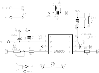
3 Tone Gong

3 Tone Gong Schematic


3 Tone Gong


3-tone-gong
This 3-tone-gong is designed to signal different driving directions in different wave forms.
This is done with a SAE800 IC.
There is a 8 pin header that is used to activate a single,
twice or three tone gong melody with active high or active low signals.
Two potis are used for volume control and pitch control.
The 3-tone-gong comes with a 8 ohm / 2W speaker.
input voltage: 12VDC - 30VDC.
power consumption: 2W

25L6 Amplifier

25L6 Amplifier Schematic


25L6 Amplifier


2 Line Mixer

2 Line Mixer Schematic


This is an image Schematic 2 Line Mixer
This simple line mixer


110 dB Beeper


110 dB Beeper


The setup employs a single 74C14 (CD40106B) CMOS hex inverting Schmitt-trigger IC, which must be used with a piezoelectric device with a feedback terminal. The feedback terminal is attached to a central region on the piezoelectric wafer. When the beeper is driven at resonance, the feedback signal peaks.

Wireless Headphone System Schematic

Wireless Headphone System Schematic


Wireless Headphone System Schematic


A wireless headphone system has recently been proposed in which a signal is ... 1 is a schematic perspective view illustrating a wireless headphone system

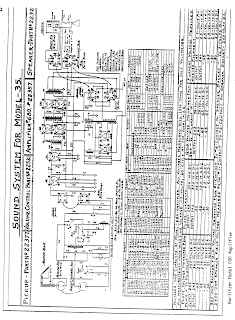
Wurlitzer 680 Schematic


Wurlitzer 680 Schematic


schematics for Wurlitzer 680
Wurlitzer Model 680 Amplifier Schematic

Yamaha AT100 Schematic

power amplifier section


pre-amplifier section


power supply


Yamaha AT100 Schematic


Yamaha GigMaker Acoustic Guitar PackYamaha at100


Keyboard Package with Portable Grand Piano


The Yamaha at100 seems designed specifically


schematic of an old Yamaha Amplifier


Yamaha BC2 Schematic


Yamaha BC2 Schematic


Free download of Yamaha BC2 Schematic


Yamaha BC2 is simply something that you blow into to control the 'breath' pressure input.

you want download Yamaha BC2 Schematic

here

Yamaha BC2 Schematic

Yamaha BC2 Schematic


Yamaha GigMaker Acoustic Guitar PackYamaha bc2


Keyboard Package with Portable Grand Piano


The Yamaha bc2 seems designed specifically .


Yamaha MFC06 Schematic

Yamaha MFC06 Schematic

Yamaha GigMaker Acoustic Guitar Pack
Yamaha YPG-635 Keyboard Package with Portable Grand Piano ...
The Yamaha mfc06 seems designed specifically ..
Yamaha MFC06 Schematic

Yamaha MPC1 Schematic

Yamaha MPC1 Schematic
parts
ic1= tdb2083ap

ic2= 74hd175

ic3= an7805

ic4= mc74hc245n

ic5= mc74hc193n

ic6= hd74hc373

ic7= mbm27c128-20

ic8= hd6303rp

http://www.freeinfosociety.com/electronics/schematics/audio/pictures/yamahampc1.gif

schematic Yamaha T50

schematic Yamaha T50

Yamaha Guitar/Bass Amplifier T50/T50C/T100/T100C

linke download
1
http://www.freeinfosociety.com/electronics/schematics/audio/yamahat50.pdf

2
Download yamaha_t50_t100.pdf.
http://www.prowessamplifiers.com/schematics/post/yamaha_t50_t100.pdf

Popular Posts